

If you’re still puzzled about the quick mold change system for injection molding machine, and not sure how to install it, go through this article to gain a better understanding of step-by-step instructions on the set up procedure. Generally, the installation guide to quick mold change system consists of 3 main body parts: preparations, installation, system debugging.
Preparations
A. Check the matching degree of ejector nozzle (this operation needs to be prepared before the template is installed)
Please check the ejector stroke, nozzle stroke, ejector hole position of the injection molding machine, and determine whether the ejection and ejection actions of the injection molding machine are affected after the magnetic template is installed. If the stroke is not enough, the ejector pin and nozzle need to be lengthened according to the thickness of the magnetic platens
B. Shut down the injection molding machine
Operator shuts down the injection molding machine and completes the following operations:
- Retract the ejector pin and nozzle;
- Demount the mould;
- Set the injection molding machine to the maximum mold opening position;
- Move the manipulator to a position where it won’t hinder the hoisting of the magnetic platens;
- Open both the front and rear safety doors.
C. Examine the product and the injection molding machine
To ensure the smooth progress of subsequent installation, please compare the parts of the magnetic quick mold change product with the injection molding machine, and complete the following inspections:
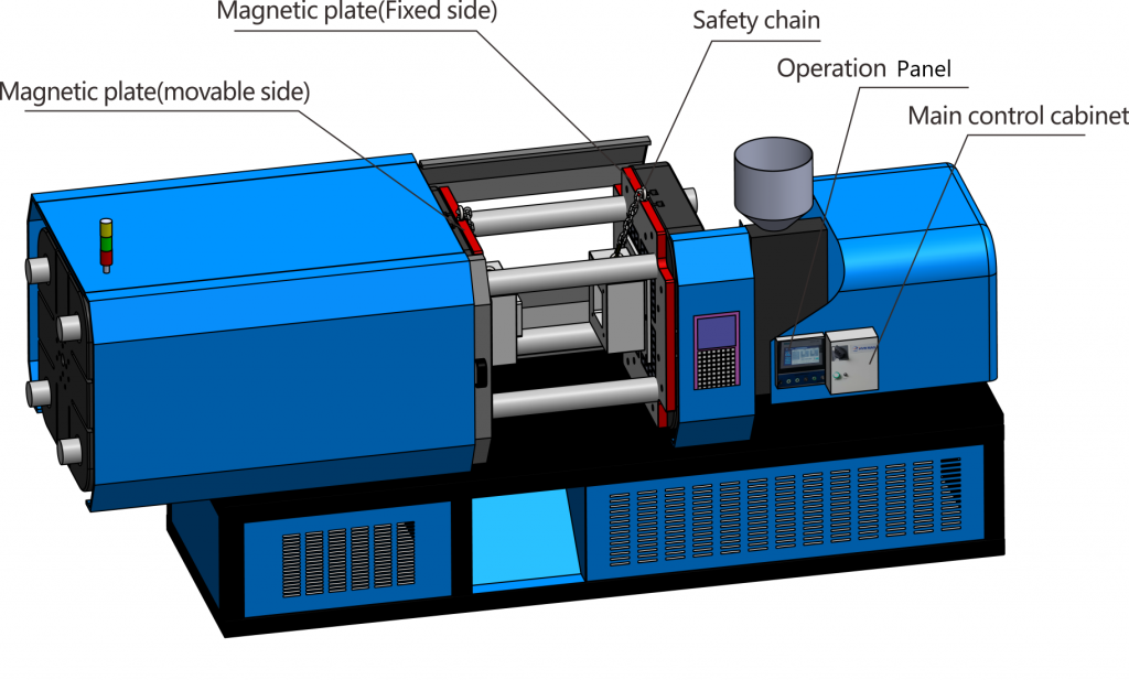
- Check whether the fixed holes of the magnetic platens (movable and fixed) correspond to the screw holes of the molding machine;
- Check whether the positioning hole on the fixed side of the injection molding machine matches the matching positioning ring.
D. Determine the installation position
- The installation positions of the operation panel and the control cabinet should be far away from oil, wiring-and-operation friendly;
- The control cabinet is generally mounted on the lower part of injection molding machine.
- The operation panel is generally installed on the right side of the safety door of the injection molding machine;
- Plan the wiring direction of the power line, signal, interlocking signal line, power line, and operation panel connection line of the two magnetic platens.
E. Clean the injection molding machine
Clean the two inner sides of the injection molding machine especially oil and rust. If the side surface is uneven, please flatten it before installing.
F. Locate the electrical connection of molding machine
Confirm the electrical connection point of the injection molding machine, see the following part for specific electrical instructions.
- Input power connection point of control cabinet
- Output point of tight mold attachment signal, of safety door closing signal
- Emergency stop signal input point of injection molding machine
Installation of Magnetic Platens
- Clean the backside of each magnetic platen to ensure no residual oil;
- Install the positioning ring;
- Hoist the fixed and movable magnetic platens into the injection molding machine with a crane; mount the fixing screws and tighten them with an extension bar;
- Vertical installation of platens for horizontal molding machine, horizontal installation of platens for vertical molding machine. Please carefully check the flatness of the two inner surfaces of the machine before installation.
Note: If the parallelism of the machine surface is not good, or with obvious obstructions, please smoothen it with a grinding device. For damaged bolts in old model machines, please re-tap the bolts to ensure that the magnetic plate is firmly fixed.
Installation of the Control System
- Drill & tap a hole in the selected installation position, and fix the control cabinet and operation panel;
- Connect the cable between the control cabinet and the operation panel;
- Arrange and connect the power and signal lines of the two magnetic platens to the control cabinet.
Power-on for System Debugging
The overall installation of QMCS is completed after all wires have been connected. Please check each connecting wire and confirm whether the power supply voltage level is correct. Then the trial operation can be started after all have been confirmed correct.
Above is what you should know about the preparations and installation guide to quick mold change system by HVR MAG. If you have any query or doubt, please feel free to leave a comment below, or contact us.


